


11/04/2023
Loadcell Usage with PLC
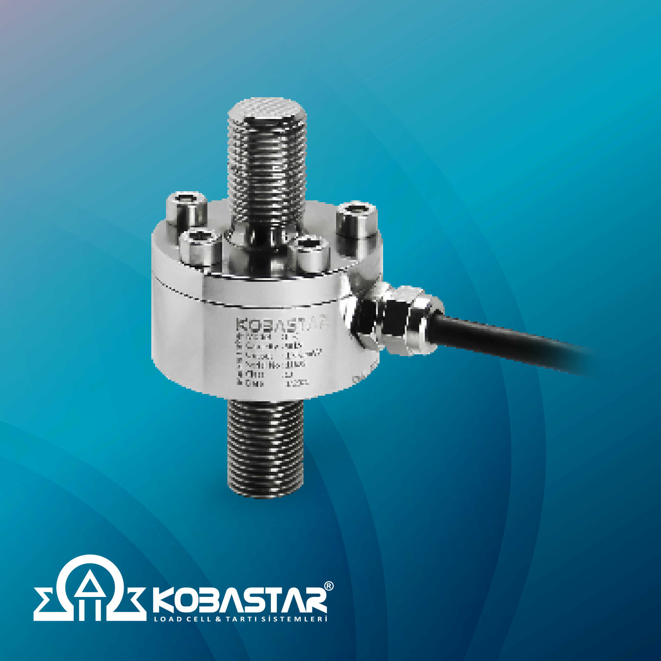
In industrial automation systems, load cells or loadcells are generally used for weight measuring operations. These measurements are often made by automation devices such as a PLC (Programmable Logic Controller). PLCs receive load cell signals, process them and display the results on the screen or another output according to the users' request.
The connection between the loadcell and PLC is made through a data bus called the signal bus. This bus operates mostly on 4-20 mA signal strength. This provides a range between 4 mA minimum signal (minimum load cell output) and 20 mA maximum signal (maximum load cell output). These signals are used to transfer data to the PLC.
The loadcell must be set correctly before connecting to the PLC. For this, it must be configured correctly according to the load cell type, load range and sensitivity. This process ensures that the load cell always makes accurate measurements.
When the load cell is connected to the PLC, the PLC software reads the load cell data and uses them for predetermined operations. These operations may include filtering the load cell signals, calibrating them, and generating a result output.
The load cell data is first sent to the PLC as an analog signal. The PLC uses an analog/digital (A/D) converter to process this signal. This converter converts the analog signal into a digital signal and puts it into a format that can be more easily processed by PLC software.
PLC software is often specifically programmed to be able to process load cell data. These programs are used to filter, calibrate, measure load cell signals and display the results. These results are displayed on displays or other outputs that are made readable by users.
PLCs can process load cell data very quickly and are therefore ideal for industrial measurements.
When using Loadcell with PLC, there are also some features in processing signal data. For example, functions such as signal filtering, linearization, biased and unbiased measurement, biased and unbiased hysteresis compensation can also be programmed. Additionally, since PLCs often have built-in programming languages (especially Ladder Logic), advanced functions can also be programmed using these languages.
However, there are some difficulties in using Loadcell with a PLC. For example, the PLC must be programmed correctly for correct operation. Additionally, since PLCs are generally designed for industrial automation applications, they may not be suitable for smaller-scale applications.
Using a Loadcell with a PLC is very useful for industrial measurement and control applications. However, they must be programmed correctly and configured appropriately.